And so it begins
Posted on January 12, 2019 by Niek Nijsen
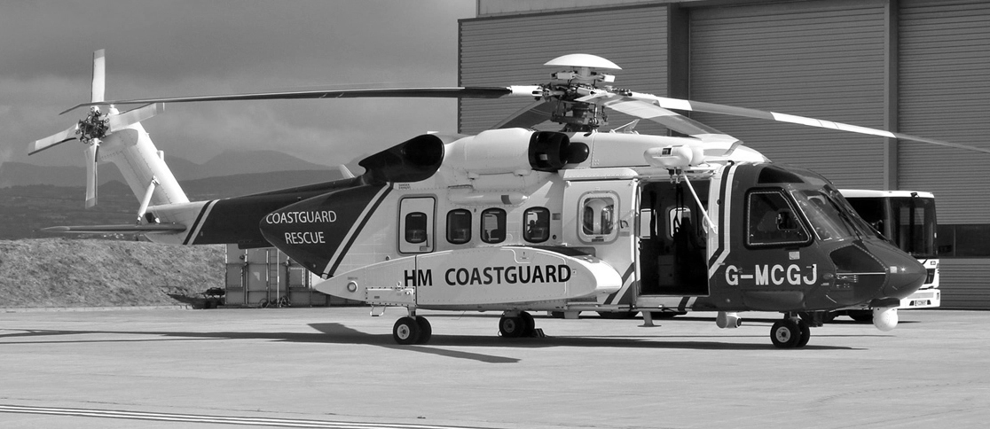
Welcome to the first update on my new project! I absolutely love you all for following my build and sticking with me on this journey, I know it'll be a long one (to give you an idea, this update alone took me roughly 30 hours to research and build). So, let's begin!
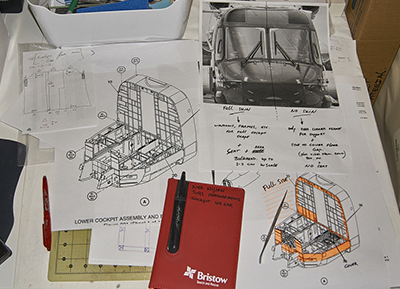
Over the last few weeks I’ve been measuring parts of the cockpit and comparing them to schematics I’ve received from our engineers (some of them were enlarged for ease of use and better detail). I figured the easiest way to get started with this project is by making the floor. That way I’ve got a solid base to build things on, plus it gives me a good estimate of final size. After many hours of measuring, converting, and re-measuring, I got some lines on paper to make a template. This was then transferred onto the 4mm thick styrene sheet that I’m using for the floor and right-hand side bulkhead. Reason for this is because the thickness will give it the stiffness it needs once everything else is added on top (especially with the overhead panels being supported by it). Basically I’m cutting the cockpit in half, the right side with the outer skin, the left side completely open for easy viewing.
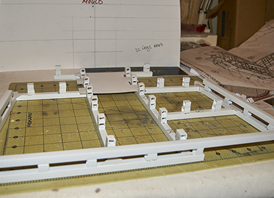
With the floor template done, I had to make the base support for the model, which lifts the floor high enough for the entrance step, but also houses all the electrics that will be fitted later on as part of the lighting setup I’ve got in mind. I cut styrene beams to size using the floor template I made from cardboard. The glue joints were strengthened with triangles cut from 1mm styrene sheet. The height was created by cutting small bits of beams and glue them together, which happened to give me the height I needed without any further modifications necessary.
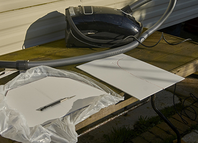
With the floor structure ready, it was time to cut the actual floor from the 4mm styrene, as well as the right-hand-side (RHS) bulkhead. My first attempt with a jigsaw resulted in something I hadn’t really thought of… heat. As soon as I cut the styrene, it would heat up so much it simply melted back together again. It even melted the saw blade along with it, resulting in me having to cut it free before being able to come up with an alternative. And you can probably guess what that would be… Back to the old fashion way of using a small hand saw. What I hoped would take me a few minutes, became a few hours job. Once I cut both pieces, I sanded them to the correct shape using various sanding sponges and sticks.
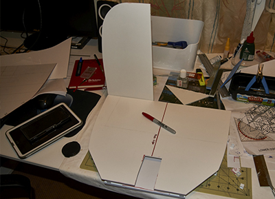
Once back at the bench, I married the floor with the support structure and placed some heavy binders on top. Stupid me decided to use a different type of glue which would provide me with a stronger bond, only to realize afterwards that it takes 15 hours to dry. Guess that was my day of modelling done. There’s a photo in the gallery that shows you a dry fit of the floor and bulkhead with a sharpie pen on top to give you a sense of size.
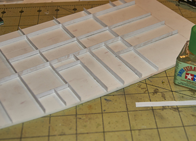
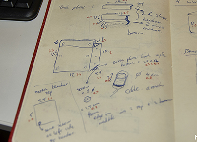
I decided to begin with the bulkhead instead of the main cockpit items. Before I could make any of the parts, I spent a lot of hours (roughly 3-4) in the actual aircraft measuring all the ribbing and components that form the entire assembly of the bulkhead. This was then all drawn out onto paper and dimensions were converted to scale. I then transferred the drawing onto the styrene part using a ruler and pencil. These lines for subsequently scribed with a p-cutter to allow for better adhesion and more ease of keeping the 5mm strips in place. The strips themselves were cut from 0.5mm styrene and glued into place. Lastly I used plastic putty in every corner to recreate the welds that are present in the real aircraft.
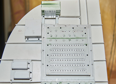
Up next is the biggest part mounted to the bulkhead, the circuit breaker panel. Both pilots have one of these behind them, as well as another in the middle of the cockpit above their heads. All good fun, until you realize I’ll be making 178 of the little fellas in the near future to go onto these panels (luckily I can leave the additional 98 located on the LHS as this side will be left open). Again the main parts were cut from 0,5mm styrene sheet. A small rod was used to recreate the hinges at the bottom which was then scribed with a razor saw for better effect. Next I made the front plate, which has all the writing on it. The writing itself will be done using decals which I’ll be designing in photoshop at some point in the future. I used a 4mm punch and a knife to cut the bits out that house the actual breakers themselves. The holes were drilled out with a 1mm drill (I will probably have to redo them with a 2mm drill, unless I come up with a different way of mounting the breakers). Further holes were drilled for the screws that hold in in place in the real aircraft. Instead of trying to make my own screw heads, I did some measuring and found that M1 and M1,2 size screws have the correct size heads on them. So off to some Chinese shop online that sells all of these, with all the different types of heads I’ll be needing (cheese, star, torx, etc). These were glued in place where possible, as I’m still waiting on the arrival of a few more that will be added once they’ve arrived. A few hexagon heads were made from styrene using a punch for further detailing. The bar at the bottom was made of 3.2mm styrene tube, which is there to stop the seat from hitting the breakers when the pilot is sliding it backwards.
The two boxes halfway up (photo with the black boxes and blue stickers on them) are the “control units for the cockpit light dimming system” (now that’s a mouthful for you). Using styrene sheet, beams and L-shaped pieces, I recreated them in scale. Pretty straightforward, but quite laborious to do which took me several hours to complete. Wiring still to come at some point, I’ll have to paint the whole lot first.
The next big box on the wall is the “Cockpit lighting control unit”, which is housed further up the bulkhead, almost at the top (photo with the black box without any stickers on it). This one was made in the same fashion as the other two, again taking several hours to make (most of the time is taken up by sketching the parts and transferring all the measurements onto the styrene in order to cut them). The wiring and decals will be added in the near future.
I thought it was time to spice it up a bit and make a circular part instead of the boxes I’d been doing so far. Although I’m not able to make the entire structure that’s mounted to the side wall, I figured I could begin with the tubular shape of the “side-window de-mister/heater”, mounted behind each pilot’s seat. I was struggling to come up with a way to make this part, until I found out that the 1/35 Hind rocket pods, which I still had left from an earlier build, were the exact size I needed. Both halves were glued together and all the surface details were sanded off. The real part is a hollow tube, which I made by cutting a piece of styrene in the correct diameter and glued that to one side. A smooth joint was achieved using plastic putty and a fine sanding stick. The other end, which has a slightly bigger diameter, was made by cutting an additional 12 (!) circles from styrene which were glued together. The whole thing was subsequently covered with putty and sanded smooth. The hose that feeds the unit with warm air from the engines will be added later, got to find the right size wire somewhere first.
More boxes to be made, this time it’s the “Window anti-ice controller” (black box with the silver sticker on it), which is located at the far top of the bulkhead, above the circuit breakers. The box itself was pretty straightforward, however the support frame required a bit more fiddling. With ribs being only 3mm in size, it took a few attempts (and a number of curse words enough to fill a novel with) to get it right, but I think the end result was worth it. The whole lot was then enhanced in detail by adding screws and glued to the bulkhead.
I wasn’t sure if I wanted to paint the bulkhead first, before adding all the parts mentioned above, but figured I could still paint everything with them in place. So they were glued on and a few more screws were added to finish off the detailing. And there you have it, the bulkhead slowly taking shape, ready for paint before continuing with the remaining items.
Hopefully I’ll be able to paint this week, allowing me to continue with the assembly asap. Thank you all for sticking with me, love to hear your comments and thoughts on this! See you all at the next update!
Return to Previous Page
Niek Nijsen Ltd.
Comp. Reg. (UK): 13778584
VAT. Reg. (UK): 398 4757 24
info@nieknijsen.com
Copyright
Niek Nijsen Ltd. © 2008 -
All Rights Reserved
Privacy Policy | Terms of Business