Powerrr! ...And lights
Posted on December 20, 2022 by Niek Nijsen
Welcome to the next instalment of this super build. It’s been a while and I figured I could probably fit one in just before the end of the year. At least you’ve got something to read while you’re laying on the sofa with too much Christmas food in your belly. So, last time I left you with a small list of things I wanted to do next. Over the months that followed (yes, it’s been that long), I modified it slightly, which brings us to this update. Enjoy!
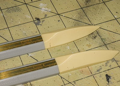
The horizontal stabilisers are now all done. Once the filler had dried, I sanded it all smooth and re-scribed any panel lines that were lost in the process. Both are now ready to be fitted and painted once the rest of the jet is done. I’ve put them into long storage obviously, as we both know the jet won’t be anywhere near ready for paint anytime soon…
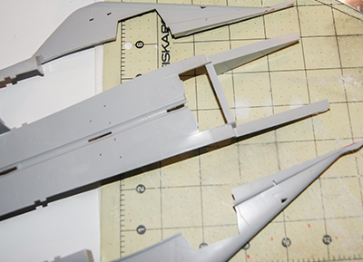
The idea of starting the second wing didn’t really sit well with me after having done the first in the previous update. For some reason, I felt that all these sub sections didn’t really add to the overall progress of the model, in that I would end up with loose parts everywhere without having a real “body” to mount them to. So, I changed my mind and figured it would be better to focus on the main part of the aircraft. And where better to start than the cockpit?
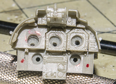
Up until now I’ve been putting off this behemoth task, primarily because I wasn’t sure how to achieve the best result. I began by laying out all the parts on the desk: standard cockpit parts, resin replacement, PE instrument panels, and LED lights. Somehow, all of this had to come together to make the best cockpit possible. At first, I was very reluctant to drill holes in the resin cockpit version, because there was a big chance of damaging the delicate parts to the point, I would lose all the added detail the resin brings. Could I perhaps do a hybrid instead, where I use the kit’s instrument panels to drill holes and then use resin for the rest of the pit? After various trials with dry fitting the parts together, I concluded that this wouldn’t work. Okay, what’s next? Could I perhaps find a way to drill holes in the resin instrument panels, and use decals to cover the screens in order to light them up? The PE panels would then become obsolete because they don’t let light through. Having had a good look at the decals that come with the kit, this might actually seem like a plausible option – Let’s keep that in mind for a minute. What about the rest of the cockpit? I really like the look of the PE side panels which have an incredible level of detail (and come pre-painted!). But the downside is that they’re all flat, with no switches and knobs as you would find in the real aircraft. Oh wait, I bought those fantastic 3D printed ones that would work perfectly for this! I’ll just glue them on top of the PE panels. Now we’re getting somewhere! That leaves us with the interior lights, the ones that are used at night to light up the entire cockpit. References were difficult to find, and the best option came from a video game screenshot. I decided to add the “main” lights which light up the side panels for both pilots. The other lights (such as a movable one and above the main screens) were too small to recreate with either fibre optics or mini-LEDs – mainly because I wouldn’t know how to fit them with the wiring without obscuring part of the resin detail or make them look correct. A few tests proved that my idea would probably work to the level I need it to. Now comes the big moment, translate all of the above theory into the physical model.
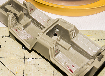
I began by carefully drilling a very thin hole through the centre of the main screens, which was done under an angle so they would come out at the bottom of the resin part. That way I could fit the fibre optics from behind and hide them in front of the pilot’s feet (which are impossible to see once it’s all glued in place). The screens were then drilled with a bigger drill to allow the light to spread more across instead of being a small bright light in the middle. I left enough space to glue a thin transparent sheet on which I can place the decals once everything is painted. The same process was repeated for the rear pilot’s screens. Next, I drilled the holes to the side of the seats which would light up the side panels. The actual lights are really nicely moulded in the resin version, and just big enough to fit the fibre optic. I drilled them out and made sure the optics would have a “hidden” route to get to them. Once all the lights were sorted, I sanded the side panels of the resin cockpit flat in order to fit the PE replacements post painting. A lot of the resin detail is kept and some of the panels will not be replaced by PE but instead I’ll paint them by hand once it's all done.
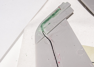
I figured I might as well stay on the subject of lights. since I’ve just managed to sort the cockpit out, I was feeling really good about myself and decided to continue with this flow by adding the lights to the vertical tail fins. This brought its own problem, because they’re so thin, I can’t sandwich the wires in-between the two halves. This became an even bigger problem once I noticed the top half of both fins are made of a single part, with no option to drill or scrape material to fit wires. That left me with only one option, and that was to create a “trench” to run the wires, drill a hole at the end for the light itself, and then fill it all up again with filler to restore the overall appearance of the part. A lot of work, but in the end, it seemed to work out quite nicely. The only downside is that the rear navigation light (the white one) was so incredibly small, there was no way for me to light this one, even with a micro-LED. I’ve tried different ideas to find a way around this, however, I think I’ll actually incorporate it in the diorama setting – How often have you had to replace a light bulb?
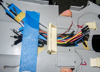
Because the connectors were too big to fit through the hole on the main body where the fins attach, I had to do the fitting of the LEDs while hanging off the main body structure. Thankfully the wires are long enough and didn’t cause too many issues (aside from the awkwardness and occasional pulling on the wire when I forgot I was pulling along the entire upper halve of the aircraft).
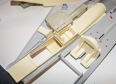
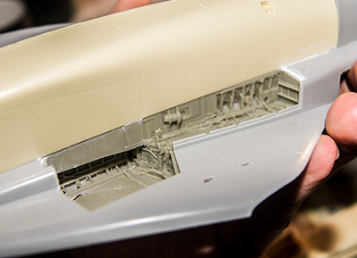
I’ve heard a lot about the incorrect appearance of the intakes and very early on decided I wanted to replace them as part of the “super build” approach. I found a company in the USA, Zacto, that make fantastic resin replacements for the F-14 and a few Russian aircraft. I bought a few more of his items, including the set to correct the weapon pallets (you might recall this from the previous update – I wasn’t sure if I had resin replacements but after going through the “project box”, I found them and subsequently changed the front two pallets), and the bladders that replace the awful rubber parts that come with the kit itself. Anyway, these resin inlets are anything but straightforward and require a lot of work and assembly in order to fit. The first step is to cut away half of the aircraft’s lower structure, which makes it incredibly flimsy and prone to breaking. It has probably taken me at least 3 hours to get the first one fitted, and I still have the second one to do (although it’s at least assembled). But the end result is more than worth it, they look absolutely fantastic and provide so much more detail.
The unexpected resin strengthening parts that came with the new inlets threw up a bit of an issue though. My initial thoughts had been to place the main light model in the centre of the aircraft, just behind the cockpit. It would provide me with the most space and it was nicely central so that all the wires would be long enough the comfortably reach it. Now there’s a large resin block right behind the cockpit, which pretty much makes the above impossible. I’ll still have to drill a large hole through the centre of it to route the cockpit wires, but the main module had to go elsewhere. The next option was perhaps in the right engine bay since it’s going to be closed up anyway. At first, this seemed like a great solution, but I soon realised that the exhaust section would be too long to fit the module in between the intake and exhaust portion of the engine, both of which I still needed to retain in order to keep the correct appearance from the outside. Long story short, I ended up placing the main module halfway in the engine compartment and the main spine of the aircraft. I’ve currently fitted this with a bit of tape, but eventually I’ll glue it in place properly once I’m happy both halves fit together perfectly with all the added internal bits.
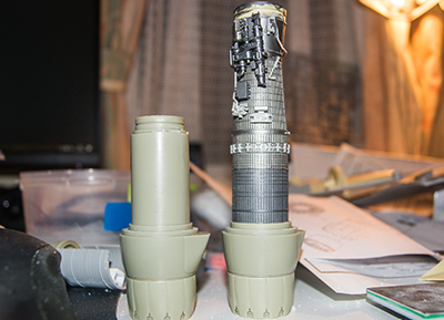
Since I was fitting the new intakes and had to figure out where the light model would go, I shifted attention briefly to the engines. I also bought the resin exhaust replacement kit, which after careful measuring, turns out to be too long. In order to get the correct look, in needed to cut down the exhaust section and glue the turbine blades in the correct position. A bigger problem came to light when it was time to upgrade the left engine, the one that will be on display. Because the resin replacement is a simple tube from the outside, I needed to carefully measure up where I needed to cut the engine’s exhaust section so it can’t be seen once it’s on display, but also that the new exhaust lines up seamlessly when looking into it from behind the model. I used the right engine (since it’s not being used) as a template and slowly cut away enough length so the overall engine length would be correct. After a few trial attempts I was happy and transferred the measurements over to the other engine, which was then cut, and the exhaust was glued on. There is still a lot of detailing work to be done on the engine itself, which will be a future update in itself, but for now the main body is looking the part and it suits my plans.
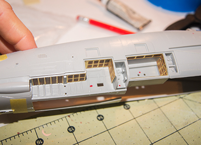
More resin replacements will be used for the wheel bays, both front and main. Since I’ve been adding a lot of resin to the cockpit, inlets, and engines, I was getting a little worried it would cause problems trying to fit these in as well. After all, none of these are designed to work together, but instead replace only a single part of the original kit and work alongside the rest of the model as intended. I can’t say it was straight forward, and a lot of sanding was required in order to get them fitted. So far, I’ve managed to get the front wheel bay in place (although not glued in as I need to paint and assemble the cockpit first), and the right rear section, which has been glued down. The next step will be to add the left intake and the wheel bay, which will hopefully be a bit easier now that I know how it goes together nicely.
I’ve also started adding PE to forward weapon section area which will be on display. The gun will be replaced by brass barrels and fitted with a lot of the PE upgrades, but that won’t happen until the front section is put together and glued in place. The parts are simply too fragile to fit now and then do all the heavy handling when merging it with the rear body section.
That’s it for now, more coming your way in the new year! At the moment my garage is too cold to spray any paint, which results in a lot of sub-assemblies waiting for spring before they can progress. Heck, I might have to start another model before then if progress continues as it has been for this update…. See you next time!
Return to Previous Page
Niek Nijsen Ltd.
Comp. Reg. (UK): 13778584
VAT. Reg. (UK): 398 4757 24
info@nieknijsen.com
Copyright
Niek Nijsen Ltd. © 2008 -
All Rights Reserved
Privacy Policy | Terms of Business